Last year, I made a pair of cam clamps to secure workpieces in my Hot Rodded Stanley Mitre Box. They were long on function but short on form, and it set me to thinking about my own personal criteria for the make-or-buy decisions on jigs, tools and shop furniture.
I realized that shop-made tools only end up in my hands if they a) are cheaper than the store-bought version, b) perform better or at least as well as the store-bought version, and c) look better than the store-bought version. In spite of my workman-like attitude towards tools, I'm surprised to find that their aesthetics are as important to me as the look of my shop or the view out my window.
As I've had my nose in several acoustic guitar-building books, it has become clear to me that I will need cam clamps in quantity if I am to proceed. I wanted to see if I could come up with a consistent method-of-work, and quantify the key elements that I've found to be critical in building cam clamps that move smoothly and lock securely. I also wanted to use only materials that were readily available at my local home center or found on the internet.
It seems that jaws that are 7 1/2" long, with each jaw being 1 1/2" wide and 3/4" thick result in a useful size for luthiery work. For the purposes of this test, I'm making some jaws from hard maple and some from white oak. I'm placing the oak on hot rolled steel bar (1/8" x 3/4") and the maple on aluminum bar (1/8" x 3/4".)
In general terms, the clamp consists of two jaws that ride on the bar. A top jaw is fixed to the bar and the bottom slides freely up and down. Pressure is applied by engaging a cam lever that, because of the placement of its fulcrum, pushes a lower arm out and pinches the workpiece against the top jaw. I use roll pins to secure the top jaw to the bar, to create a friction fit for the sliding bottom jaw, and as a fulcrum for the cam arm.
While I'm giving exact dimensions for every step, the most critical geometry comes into play around the sliding mechanism of the lower jaw and the placement and pinning of the cam lever. I'll deal with these in the step-by-step instructions and I hope that my experience (and mistakes!) will take some of the mystery out of creating a really useful tool.
Making the Parts
1. I start by milling all stock to the correct dimensions and I create identical sets of top and bottom jaws. Using the tenoning jig on the tablesaw, I cut a 1 1/2" kerf on the back end of each jaw set. As the bar stock is 1/8" thick, it fits nicely in this channel. I also cut 12" lengths of the bar stock with a pair of bolt cutters (far superior to sawing in my opinion.)
2. Next, a quick trip to the router table (with a 1" straight cutting bit) to place a relief on the inside of all the jaws. Right away, the oak gives me more trouble, chattering, and requiring three incremental passes in order to avoid tearout. The maple responds well to one deep pass. I built a cradle to hold each jaw tight to the fence and keep my fingers well away from the bit.
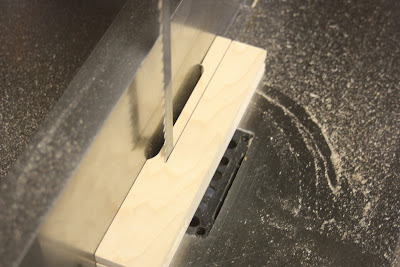
3. With the relief cut, I then take the lower jaw to the bandsaw to cut the section that will flex under the pressure of the cam. I leave 3/16" between the relief cut and the cut line and cut back to within 2 7/8" of the back. I drill a hole at the terminus to prevent the piece from splitting.
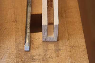
4. Switching to a 5/16" dado blade in the tablesaw, I prepare to cut the curved channel into which the cam lever will ride. I flip the lower jaw upside down and set the height of the blade to just brush against the flexible arm, I want to cut the channel 2 1/2" along the top of this lower jaw. I do this by aligning the overhead fence with the back of the jaw as it just touches the blade. I then mark on my notched push stick a line 2 1/2" back from the edge. I now know that when the mark on the back of the push stick meets the overhead fence I've advanced the jaw the proper distance onto the dado blade. Turn off the saw, wait for the blade to stop and remove the jaw. Repeat this for all of the lower jaws. I also extend the distance that the cam contacts the arm by removing some material with a mortise chisel. This increases the length of throw on the cam arm.
 |
| The mortise chisel removes material the cam lever has access to nearly 1" of the flexible arm |
5. I used white oak to create the cam levers. I start with a blank that is 4" x 13/16" x 1/4". I use a 13/16" Forstner bit to scribe a circle at one end. Using a saw, or a file, or a disk sander, remove material until a half circle remains. I then taper the cam arm to a narrower radius at the back end, but this is primarily for aesthetic reasons.
Assembly
6. I start by securing the upper jaw to the bar stock in a little jig that holds the bar at a 90 degree angle. I snug the bar tightly into the kerf
Now, drill the holes at the drill press and drive in the roll pins. It is important, particularly with the steel bar stock, to drill at a medium high speed with little pressure, to keep from bending the bit. This last piece of advice comes from experience.
Attaching the sliding lower jaw to the bar is one of the more crucial tasks in this build. If it is too tight, it will not move up and down freely; if it is too loose, it will require a great deal of throw in the cam arm to get enough pressure to secure the workpiece. Like most tutorials, I use roll pins, placed in a staggered fashion with just enough play in them to allow the jaw to slide. However, my method is a bit different as I secure one pin, check the fit, and then decide whether the friction of the bar against the end grain of the jaw is sufficient for the clamp to operate. If it is too loose, I Install the second pin, protruding only slightly into the kerf to dial in a fit. Here's how I do it.
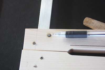
7. Slide the lower jaw onto the bar and align it so that it is tight to the back of the kerf. Using a small square, mark the back of the bar on the face of the jaw.
Drill and install a roll pin so that the edge is against this line (see the photo above.) It is crucial that it is behind the bar and aligned as above. If the clamp gods are on your side, you can slide this on the bar and it will move with the smallest amount of effort. Ideally it will hold its place on the bar when you slide it up and down vertically. If it is too tight, you can remove the jaw from the bar and file or chisel the inside of the kerf until it moves freely. If it is too loose, don't worry, we'll address that in a minute.
8. Installing the cam lever in the slot is best done in one operation (match drilling I think this is called.) It is important that you drill the hole for the cam so that it creates an eccentric circle -- meaning that as you turn the cam lever up, the effective radius becomes larger and it flexes the cam arm toward the opposing jaw. Here's an example of how it looks when completed.
This is achieved by placing the cam in the slot, with the front of the cam arm even with the front of the jaw. Drill through a spot 3/4" down from the top of the jaw and 5/8" from the front of the jaw. I have my two shop made marking gauges (kebiki) set to these dimensions for quick marking. Tape it in place and drill on the drill press.
Drive through a roll pin, slide it back on the bar, and give it a test run. If everything has worked out, when you slide it together, push a bit on the back, and lift the cam lever, it will push the arm out enough to pinch the workpiece between the jaws with a great deal of force. If it it doesn't, you can trouble-shoot these pretty effectively.
If it fails to clamp: Either the fit on the bar is too loose or the cam lever is not pushing the arm away from the clamp. Check the fit and look at how the bar moves. The easiest fix is to add another roll pin, diagonally and on the other side of the bar on the lower jaw.
The pin should be visible from inside the kerf, reducing its effective width. If it protrudes too far, you can file down the pin from inside the kerf.
If the cam lever isn't moving the arm far enough, tap out the roll pin, remove the cam lever, make another, and reinstall, allowing it to protrude from the front of the clamp when you drill.
If cam lever won't lift far enough to hold its position: It is probably too big or it is making contact with the jaw before it can fully engage. Remove the cam lever and sand a flat spot on the top of the circle. While it is out, remove more material with the mortise chisel to allow it to swing freely.
9. Using carpet tape and whatever leather you have sitting around, fashion and attach pads to the business ends of the clamps. I found it easier to attach the tape, then a slightly oversized piece of leather, and then trim with a razor blade to fit, using the sides of the jaw as a template. It's also a good idea to run a file over the edges of the steel or aluminum bar.
The clamps are now complete!
So what's the verdict on the make-or-buy decision? First off, I used nearly every one of my stationary power tools to make these clamps, so if you don't have a fully-equipped shop, I'd think twice. Also, it took more time than I thought, but I wanted to get this right, document it and have a zero percent failure rate -- and that I accomplished.
On the plus side, you can't argue with the economics. I spent approx $2.00 apiece for clamps that would have cost around $15.00 each (with shipping) and I've heard some real gripes about quality on the clamps at this price point. I made 20 clamps, so that's around $300 worth of tools. And if you told me I could build my own Lie-Nielsen plane in this time, and improve upon its quality, I'd do it in a heartbeat.
Oh, as I expected, I much prefer the aluminum bar and the maple over the oak and the steel. The maple works more easily and the aluminum is cleaner -- but because it is slick the tolerances on the lower jaw must be tighter in order to grip. Thanks for hanging in there on this long post, and please feel free to contact me if I can answer any questions or if you have any corrections.
Cheers!
Next up, the Hammer-Beam Tables begin to take shape.


Nice job Christopher! I might have to try my hand at that.
ReplyDeleteTyler
Hey Chris, funny eh, I too was recently making some 'shop made' cam clamps...you can never have too many!
ReplyDeletegood to see you back on the blog~ talk soon.
Tom
Thanks guys. They are cool little engineering marvels -- I just have to avoid the temptation to make a fetish out of them and keep "improving" them when I have other deadlines to meet!
ReplyDeleteAnother great project for my list! BTW here is a link for your blog list.... http://middlething.blogspot.com/2011/11/first-flash-from-can.html
ReplyDeleteHhhhmmm. Mr. or Mrs. Lek Furniture, I think you have highly overestimated the number of people who read my blog.
ReplyDeleteThis comment has been removed by a blog administrator.
ReplyDeleteI think I like your furniture very nice
ReplyDelete