Saturday, December 24, 2011

Contemporary Shaker Style Table -- Building a Base


Happy Holidays!

While the second step of the finish on my Hammer-Beam Tables is drying, I'll take the opportunity to post about another recently completed project.  This table is a variation on the Shaker Candle Stand idea with a couple of contemporary updates.  First, it is made primarily from black walnut -- one of my favorite woods to work with hand tools.  Second, the design of the top includes includes a strip of figured maple.  I suppose the unifying element is that all the stock comes directly from my scrap pile.

As I've posted about Shaker tables in the past, I'll review the highlights in two posts.  And remember, I'm always up for questions or discussion about the techniques.


The base begins with a turned column.  I've found that these can be glued up from leftover stock with great success.  If I use Titebond II Dark Wood Glue and try to keep the grain running in the same direction on each piece, I've never been able to see any difference between this and solid stock.  The design is simple, which just about matches my skills at the lathe.  The only hard number that I need to hit is the diameter of the top tenon that will join with the top -- and even this just needs to match a Forstner bit in my collection.  The bottom is turned with a slightly narrower diameter, the length of which matches the top of the leg.  This creates a base ridge that is the stop for the leg as it sits in its sliding dovetail.


Without removing the column from the lathe, I set up my sliding dovetail jig on the lathe bed.  I now mark the stops in the indexing head to allow me to make three cuts, dead center, at 120 degree intervals.  The first step is to create a flat spot upon which the leg will rest.  Structurally, this doesn't matter, but aesthetically it makes for a better join between leg and column.


Through trial and error, I know that I should first cut a 3/8" groove to a depth of 1/2" in a series of passes in these three places.  I follow this with one pass (at a depth of 1/2") with my 5/8" by 14 degree dovetail bit to achieve a perfect sliding dovetail mortise.


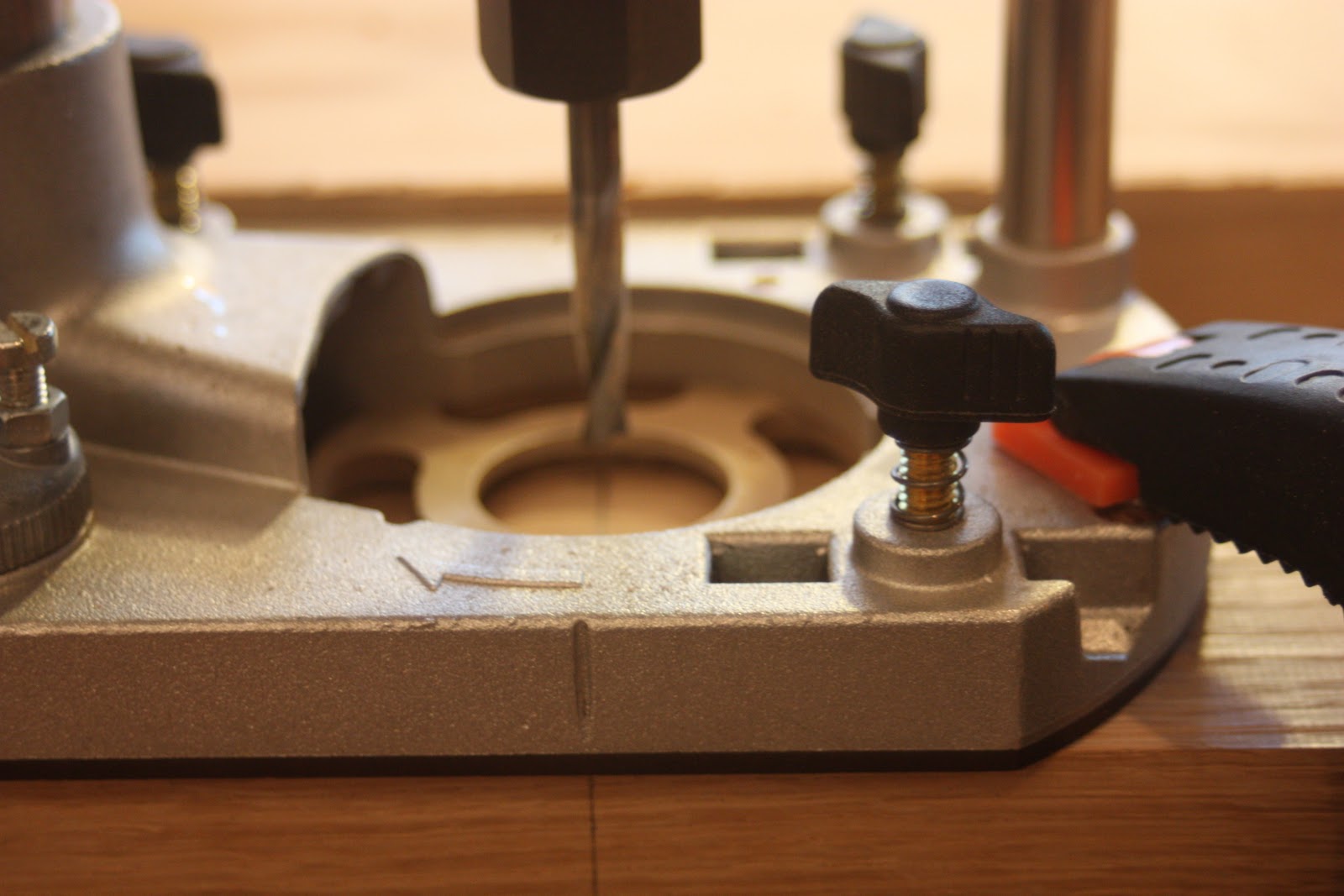
When this is complete, remove the column from the lathe and place the dovetail bit in the router table.

I've redesigned, slightly, the shape and size of the cyma-curved leg that is part of the beauty of the Shaker table.  The top is larger on this table than on previous iterations, so I've expanded the spread of each leg and reduced a bit of the bulk from my last design.  I do this by means of a pair of flexible bending sticks.  An initial drawing is made on my plywood template, small blocks are hot glued to the lines at intervals, and then the sticks are clamped to these blocks and manipulated to create fair curves.  I trace this and cut the template close to the lines.  Finally I hot-glue thin (1/16") strips of hardwood to the template edges -- ensuring a fair, bump-free, routing template.  It is important to make this template longer than the actual piece so that you can begin and end your routing without encountering end-grain.

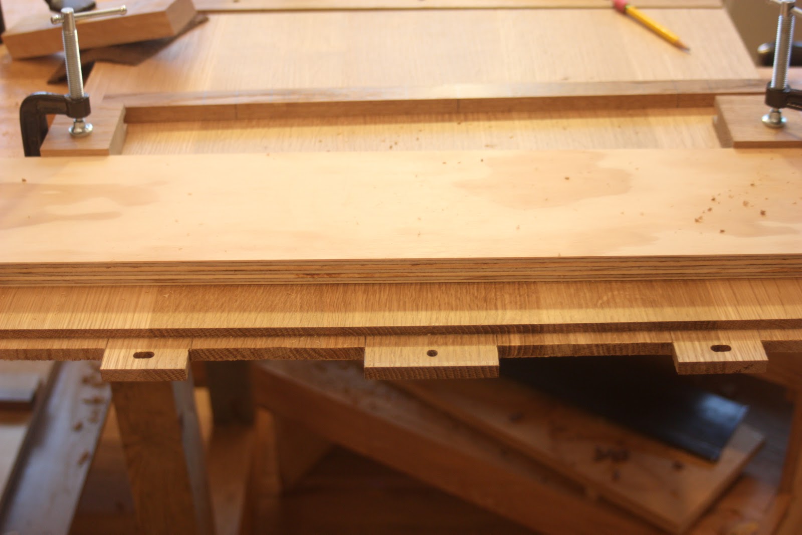
Stock preparation for the legs has a bit of a twist as well.  Once the board is planed to the desired thickness, I cut it into leg-sized lengths with a cut that is at a 30 degree angle.  This allows me to line the tenon up along this cut line and keep the grain running along the long axis.  I trace each leg onto the stock, but I do not cut it to shape yet.  This allows me to machine the tenon at the router table with a wide bearing surface.

As usual, you use a piece of spare sock to dial in the thickness and depth of the sliding dovetail tenon.  This is a very sensitive part of the build -- one or two mm can be the difference between a good fit and firewood.  I like to err on the too-tight side and take a couple of passes with 220 sandpaper to get perfection.  I also strike a line with a cutting gauge along this cut.  At this angle, and with walnut in particular, you will get tear-out unless you take this precaution.

Only now do I take it first to the band saw, and then back to the router table to bring it to final dimension.


I trim the top and bottom of the tenon and round the top portion to match the round mortise of the column.  The actual stop for the mortise is the flat top of the exposed leg above the tenon.  These should be trimmed to the same length, and to the thickness of the base ridge to achieve a good fit.  Now all that is left to do is put together your first trial fit.


I'll wrap this up with one more post about fashioning the top and applying the finish, as well as a wrap of the Hammer-Beam Tables.  Cheers

Thursday, December 15, 2011

Workshop Tips You may Already Know -- Installing Metal Threaded Inserts, Correctly!


Recently, I was searching the web for something or other, (a video of a porcupine who likes corn? a Lance Link: Secret Chimp lunchbox?) and I came across this video.  At first I thought it would be about as useful as the instructions on a bar of soap.  I mean, C'mon how hard is this?  Sometimes the screwdriver breaks the top while you are bearing down, and they always seem a little tight, but this is intuitive, right?

I use threaded inserts when I attach table tops to their base, (this is called foreshadowing) and they look good when they don't snap in half.  Which for me, is too frequently.

Well, the tagline that shouted "YOU MAY BE DOING THIS INCORRECTLY!" drew me in -- and sure enough, I had been doing it incorrectly.  The video explains the correct technique much better than I could, and armed with this new knowledge, I sheepishly gave it a shot.  I'm happy to report that, indeed, that is not a screwdriver slot on top and that the drill press works a treat for providing even pressure while you turn the wrench.  Go figure.

So in case I'm not the last person to learn this, enjoy!  If I am, well, it won't be the first time I was a bit behind the times.  I'm still wounded by the experience of showing up on the first day of school with a Lance Link: Secret Chimp lunchbox and everybody else had switched to carrying their sandwiches in paper bags.

Friday, December 9, 2011

The Hammer Beam Low Table . . . Making Breadboard Ends


We're on the homestretch now, with the table flat, the base built, and the scent of TransTint is in the air.  I really enjoy making breadboard ends -- the process is very tactile and represents everything that is good about hand-made furniture.  As with most joinery, it helps me to start with a known dimension for the "mortise" element and then dial in the fit of the "tenon" element.

The thickness of the top is approx. 7/8" so I'm going to go with a tongue thickness of 3/8".  I will cut this groove, on visual center, on the breadboard end piece that is about 1/16" thicker than the top.  I say visual center as I just eyeball this on the router table.  Inevitably, one cheek is ever-so-slightly thicker than the other and I orient this on top to ensure that I cover the end grain of the table field.  I may be over-cautious in this regard, but coming up too thin on the top is an automatic reboot in the process.  I cut this to a depth of 1/2" on the router table.

Setting this aside, I begin to create the tenons on both ends of the table top.  I make a rough and ready jig that sandwiches the top between two pieces of plywood that creates identical fences on both sides of the board.  I measure back from the edge, with the bit in place so that it will cut a 1 1/8" tenon.  I then make a spacer block of this width that will align the jig to the correct distance from the edge every time.


I measure the width of the cheek on my mortised end piece with digital calipers, reduce it by a few mm, set this as the final depth of the router, and cut to completion in several passes.  I reduce it by that little bit to ensure that the end piece will stand proud of the table top.  With the dual fence in place, I flip the piece and rout the other side to within a few mm of completion.  Checking the actual fit with the end piece, I continue until there is a snug fit.


Now I make my story stick for the tongue. The tongue features three longer tenons that will be 1 1/8" in length -- adding the real stability to what is by nature an awkward cross-grain situation.  These tenons will be pinned with a dowel through the end, and depending on the orientation, the holes for the pins will be widened to allow for wood movement. I lay out the tenons symmetrically so that if it gets accidentally rotated 180 degrees between passes on the router table, the piece will still fit.


I mark the tenons and cut them out by hand.  From the tenons I mark the corresponding mortises on the end piece, adding approx. 1/4" on the two outer mortises to allow for seasonal movement.  I then return to the router table and "plunge cut" these mortises against the fence (I'm not detailing this procedure because I'm not sure if it is a good practice -- proceed at your own risk.)  A quick dry-fit lets me know that I am on track.


As you can see, I've cut the end boards slightly thick and overly long to allow for an exact fit.  My next step is to trim these ends, along with about 1/8" from each edge of the table top, to bring to the final dimension.  As my sled isn't large enough for this piece, I friction fit a spacer between the two end boards and run this edge along the table saw fence to the correct size.  Once one side is cut. it can run along the fence to cut its opposite number.


Using my 4 1/2 smoothing plane, complete with high-angle frog, I then plane the top of the end board to match the height of the table top.  I find that if I keep the end board attached to the top, pulled away by about 1/2", I can plane without the risk of making a cross-grain gouge, and monitor the fit with a square.  In practice, I leave the end board just fractionally proud.


 With the edges cut to fit and square, all that is left to do is to pin the end boards to the tenons with dowels in a manner that addresses the cross grain nature of this joint.  I find that a plunge router acts as portable drill press, positioning the hole very accurately and spinning the bit at a speed that discourages tear out.  While it might seem intuitive to use the edge of the end board as a reference for plunging these holes, I've found a method that I like better.  If you create a fence that is attached to the table top, you can drill the holes through the end board and tenons in one go, remove the end board, widen the two holes on the outside by about 3/8", without readjusting the fence.  This gives you a very clean channel for the dowel to ride in during the table top's seasonal journeys.

The best part of this is that you have already built the fence.

I start by marking the dead center of each tenon on my story stick and transferring this line to the end board. Using the jig I created to cut the tongue mortise, as well as the spacer block, I reset the dual fences in their original position relative to the ends of the tenons and clamp them down.  I dry fit the end board in place and add a 1/4" spacer strip to the fence. Why the spacer?

Using the jig without a spacer would place the bit dead center of the 1 1/8" original width.  Experience has taught me that this is too close to the short portion of the joint.  Pushing it out 1/4" places the hole completely in the long tenon portion of tongue.  This is better both functionally and aesthetically.  Now insert a 1/4" spiral bit and plunge through the three marked holes for the dowels.


Remove the end board, and expand the two outside holes to create a channel somewhere in the vicinity of 5/8" wide.  Now, the top is free to expand with the heat and humidity of summer, and contract in the winter dry spell.


The final step is to re-install the end board and peg with the dowels.  I place bit of glue only on the center tenon and reassemble. Using  a cotton swab, I coat the inside of the center hole with glue, dip the peg in glue, and drive it home.  The excess glue will fill any gaps created by slightly out-of-round dowels.  Reaching from underneath, I place a bit of glue in the outside holes, but only deep enough to coat the bottom cheek portion.  I drive a peg 3/4 of the way through, apply glue to the top of the dowel, and drive it home.  My objective is to keep any glue from traveling down to the tongue portion of the joint.  In all fairness, I'm not sure if excess glue would cause a problem, I just want to ensure that the joint will work properly.


After this cures for a few hours, I trim the dowel with a Japanese flush cutting saw, take a few passes with a block plane, and finally make a couple of passes with some 220 grit paper to make sure that I've removed any excess glue and to clean up any "bench rash."  be sure to take care when using the delicate flush-cutting saw on the white oak dowel.  I've read that this saw is not really designed to cut tough American hardwoods, so a light touch is important.

Several times along the way I used my smoothing plane to clean up the surfaces.  In a couple of spots I pulled out the shoulder plane to fine-tune the intersection of the end piece and the table top, and I finished the ends of the end board with a few passes on the shooting board.  All of this is intuitive, and you won't go too far wrong if you go with your gut on these decisions.

This turned into a much longer post than anticipated, and I'm sure that I've left something out.  Please feel free to shoot me a note i if you have any questions or see a better way to approach this most satisfying part of this project.  Cheers.

Next up:  Final construction and a bit of finish.

Saturday, December 3, 2011

The Hammer Beam Low Table . . . Flattening a Table Top with a Hybrid Approach


I often wonder whether my procedure for a given task is the "right" way to go about things. I suspect that I'm not alone in this feeling.  Woodworking magazines make it seem very arbitrary - creating a linear approach that gives consistently good results.  And that works well, up to a point.  On the other end of the spectrum is an approach that says "I'll let the wood be my teacher."  You experiment with a number of known techniques until the wood yields the outcome you desire -- and those techniques may vary given the wood species, your mood, the weather, and the application.

As a hybrid hand tool/machine woodworker, I'm comfortable moving forward with my preferred method (generally hand tools) but jumping ship the minute the going gets rough.  This is how I approach the all-important flattening of a table top.

It starts with two things:  a Number 12 Scraping Plane and an open mind.

That's not quite fair, it actually begins with a sense of what's possible and important during glue up.  I always orient my boards with the grain in one direction in order to keep the option of hand planing to completion in play.  This limits my design choices a bit, but I've not found that to be too onerous.  Depending on the species, whether I'm re-sawing, and my deadline, I machine-surface my stock over a series of days.  Hopefully I can keep any post-planing movement to a minimum.  I try to bring the machined thickness to somewhere around 1/16" above my goal, but I've not been in a situation where (within reason) final thickness was visually critical.

This is a five board glue-up, and I do it in two steps.  Perfection is the goal, but I've found that it is nearly impossible to fully correct any bend down the long dimension. You must keep checking the joints to see that they are even and use a straightedge across the boards ensure that they are not cupping.  I use bog standard pipe clamps since I find them easier to adjust than Jorgenson clamps.  My experience is that in spite of your best efforts, the wood will want to move to its own stasis point.  Forcing joints closed with too much pressure can result in instability down the road.  If things really start to go pear-shaped, I stop, scrape off the glue, and think about resurfacing/rejointing the boards.


My finished glue up (I'm doing two tables at once) looks like this.  It is not perfect, but it is within my own personal tolerances for quarter-sawn white oak.  For the record, I find QSWO to be prone to movement after cutting and surfacing, and sometimes balky to finish with a hand plane.

Once out of the clamps, I have a go at all the glue lines with a card scraper -- doing this while in the clamps and the glue is gelatinous is even better.

It has taken me a long time to understand fully the real difference between Flattening and Surfacing.  The first, Flattening, has much more to do with geometry (is it level, across all the boards, with no variations between each board.) It is a prerequisite for Surfacing which has to do with the texture of the flat surface.  In this case there are ridges on the boards, and in some places the variation is around 1/64" of an inch. I began flattening with my Number 12 scraper, equipped with a Hock blade. The blade is honed to a 45 degree angle (with no hook), and I lean it well forward.  Moving diagonally, but with the grain, I come from two directions -- creating a crosshatch pattern and removing stock at a pretty good rate.

I prefer scraping to planing with a jack plane.  In my experience a scraper will only dig as deep as the blade is set (in this case, the thickness of a paper towel) without any real risk of tear-out.  I'm sure that there could be a long discussion here about "type 1" or type 2" chips, toothing planes, and scrub planes -- I'd I'd like to explore that -- but this is what I know and it works for me.  I'm looking to create a uniform cross hatch pattern that touches all surfaces of the wood.


I also look at the quality of the scraping to make sure that it is fluffy and long (not chunky or just dust) and adjust the scraper accordingly.

Once I'm pretty sure that the high spots have been brought to the level of the low spots I remove the blade, hone it, and set it for a very light cut.  I now go with the grain and remove any ridges left by the diagonal scraping.  I have found that this is an important step, and can save a great deal of time when I begin surfacing.  Finally, I break out my 5 1/2 bench plane, set for a light cut, and begin first diagonal then straight passes with the grain.  I'm hoping that with this light cut I can plane with no tearout.


. . . And right away tear-out begins to appear on one board.  I quickly switch to my high angle 4 1/2, and though it is better, tear-out continues.  I even give my low-angle jack a try, but it is no better.  For the record, I have found that this light-colored, slightly stringy oak can be difficult to work.  Using a card scraper, I surface the wood to a depth below the tear-out.  I suspect that with ultra light cuts I could get the rest of the surface down to this level, but I'm not up for the task.


Breaking out the RO sander, I begin with 120 grit paper and in about 15 minutes have the surface completely finished to 220.  It could have been done more quickly if I could have found any 80 or 100 grit paper in my mare's nest of a sanding cabinet.  Was this my first choice? No.  Would I have preferred to finish this with my 4 1/2 plane?  Absolutely.  But I'm long past the idea of pursuing a course of action simply because I want to prove to myself (or the hand tool orthodoxy gods) that I can complete the task with style points intact.  I'm interested in making furniture, not making a point. Now all that is left to complete are the breadboard ends.

I'm curious to hear about your procedure for table tops and results and style points.  Cheers!

Sunday, November 27, 2011

The Hammer Beam Low Table . . . Creating Corbels and Making Sliding Dovetails

With the greater part of the base complete, it is time to tackle the decorative corbels that adorn each foot of the table.  I began with the idea that a stacked and constructed piece, incorporating a large tenon, would add visual flair and lock the curved beams in place.

I construct each corbel with five small pieces of stock -- a tenon, an upper internal piece, a lower internal piece, and two external cheeks.

The tenon and the internal pieces ready for glue up.
As the individual components are all small, I use "rub joints" and line up the pieces by eye. I start with a sub assembly of the internal pieces and add the external cheeks once these are dry.


Using my initial drawing as a guide, I place an arm on my bandsaw's circle cutting jig and set the it for an 8 3/8" radius cut.  Aligning the drawn piece against the curve, I'm able to hot-glue two stops on the jig to transfer this curve on the glued blocks.  A bit of carpet tape holds the block in place and they pop out of the jig nearly complete.  A quick chamfer on the front edge and a bit of sanding results in a finished corbel.

The end grain was sanded quite easily with the pneumatic sanding attachment on the drill press, and as I'd already checked the fit of the tenon in the base unit, everything came together with just a bit of work with the shoulder plane.

I'm joining the two base assemblies together with a stretcher that attaches with sliding dovetails.  I always enjoy making sliding dovetails.  There is a great deal of instant gratification as the pieces come together in a perfectly fitting joint.  It also helps that I have a method, and a pair of bits, that make it very easy.

The stretcher is 3" wide and will attach dead center at the top of each base assembly.  Because I want this to be a stopped mortise, I will only cut the groove about 2 1/2".  I start by finding center on the mortise stock and begin to make a 3/8" groove on the router table.  I bring the depth to 1/2" in a number of passes.  Experience has taught that if I create this groove, and follow it with a single pass with my Lee Valley 5/8" x 14 degree dovetail bit (#16J1755), set to a depth of 1/2", I get a perfect sliding dovetail mortise without stressing the bit with too much stock removal.  The only challenge with this technique on the router table is that you must make the bit change in a way that allows you to keep the fence in the same place.

The advantage to the router table is that once you have made the pass with the dovetail bit in the mortise, you have automatically set the right height for the bit to cut the tenon.  All adjustments to the width of the tenon will be made with the fence. I like to start by marking a deep mark in the tenon stock with a gauge to help eliminate tear-out.

I adjust the fence, using test stock of the same thickness and with passes on each side, until I have a snug fit.  Patience is key here as you dial this in -- one overly-ambitious cut and you will need to start over.  Using a jig, or your own steady hand, cut the tenons to size.

As these are stopped joints, you will need to remove some stock from the tenon to complete the joint.  I start by sliding the tenon into the mortise until it stops.  I set my gauge to this depth, mark the tenon on the bottom of the stretcher, and remove with excess with a hand saw.

 
Although this joint will never be seen, I do get some weird kind of satisfaction as it comes together without a hitch.


In order not to bore you (too much!) I did gloss over some of the specifics of how I went about these parts of the project -- but I'd be happy to go into more detail if you have any questions.  I'm also open to being shouted down if you see some glaring error, or know of a better technique.

Next up -- the breadboard top.  Cheers!

Monday, November 21, 2011

Workshop Tips You may Already Know -- Drilling Perfectly Centered Holes


I'm often the last to discover a brilliantly simple method for overcoming some devilish workshop problem. So, in case this little technique isn't in your bag of tricks, I thought I'd pass it along.

Say you have to drill a hole through stock that is one diameter on the entry side and a second diameter on the exit side.  To make matters worse, there is no square reference surface to place against a fence, and you cannot tolerate any tear-out on either face.  This situation presents itself when making an electric guitar with a string-through bridge -- the strings come through the metal bridge, enter a 1/8" hole, pass through the body, and exit a 5/16" hole that contains a ferrule.

There are many ways that you could attempt this, but this method is foolproof.  Start with template with holes that match either the entry or exit hole dimension.  In the case of a guitar, the metal bridge works a treat.  Position the template on the correct side and affix using carpet tape.  Using a drill press, and allowing the bit to find its way into the template hole, drill most of the way through the piece.

The key to this technique is a purpose built jig with a post that matches this first hole.  In this case I use a small length of 1/8" steel rod and allow it to protrude from a piece of MDF by about 1/2".  Now, making sure that you have enough clearance between the bit and the jig (to allow sliding in the workpiece before plunging for the hole), center the bit on the post.  Insert the bit for the second diameter and double-check that the bit is still centered.


Now it is just a case of placing each hole over the post and drilling to the proper depth.  The resulting holes will be centered over the smaller holes, and keep the perfect alignment of the template.  One caveat -- place a thin piece of waste board on top of your stock when removing it from the post.  The snug fit can (will) make you pull hard enough to recoil the piece right into the bit above.


This technique comes from the archives of TDPRI -- a great source of information for building Telecaster-style guitars.  BTW, I'm finding loads of tips from the guitar-building world that have broad application in making custom furniture.  So I'll pass them along from time-to-time.

Cheers!

Tuesday, November 15, 2011

The Hammer Beam Low Table . . . Building the Base


There are many reasons to avoid designing and building simultaneously.  Materials and time may be wasted, and there's no guarantee that the whole thing will hang together -- visually.  But it does give you the maximum degree of flexibility for the greatest amount of time.  After fiddling with the design on paper, I decided to flip the entire piece and and place greater visual weight along the floor.  I wasn't exactly sure, as I started to saw the white oak, how the joinery would come together -- but once underway, it became pretty straight forward.

Given that I'm looking to give the appearance of post and beam construction, I knew that each piece would be fairly thick, and given that I didn't want to invest in 12/4" timber, I knew that I'd be gluing up for thickness.  This gave me the chance to "build" more complex joinery in pieces, simulating large mortise and tenon joints without all the chiseling.


I start by gluing up three pieces to make the vertical post.  Because I want to create a shadow line against the bottom support rail, I sandwich a 3/4" thick piece between two 7/8" pieces.  I take care to keep the grain running in the same direction to facilitate the hand planing that blends them into one visual post.


This support rail is an odd-looking little construction (3/4" thick), that will slide into the post's bottom. creating a bridle joint of sorts.


I then attach a series of 3"x7"x 3/4" "cheeks" that make the rail look to be one solid piece.  As long as every cut is square, you create a perfect 90 degree angle.  As all glue surfaces are long grain-to-long grain, I'm not worried about the strength -- but they will be reinforced later.  Once dry, I'm ready to move on to the curved "supports."

I drew the curves using the method outlined in the contemporary chair project -- attaching flexible bending sticks to a block the width of the leg, and moving it until I had the curve I liked.  It's then into pattern-making mode to cut and refine a template that reproduces that pattern.  I remember to make the template longer on both ends to facilitate the entry of the router bit without encountering end grain.

As I want the final thickness of each support to be approx. 2", I select some chunky 8/4" white oak stock. I Surface, bandsaw, and template each piece, arranging the stock in such a way to avoid routing against the grain.  I do not cut the straight sides with the router, rather I plane to the line on the long straight side, and cut the bottom of the support with a newly-sharpened saw.


A quick pass with a my 4 1/2 plane over this very straight-grained oak results in a glass-like finish.  I've found that adding a high-angle frog to the mix improves almost all of my smoothing jobs,


The support is joined to the post and rail by a joint (that must have a name), that slides along a loose tenon on the post, and is fixed to the rail by means of a dowel.  There will be a corbel that attaches in a very robust fashion that will also secure this piece.

The support on the right will slide along the tenon, cut to provide a long grain-to-long grain strength . . .  

. . . and the dowel pops into place
The next step is to create the corbels that will act as feet on the table, provide visual interest, and secure the supports.

Cheers!

Tuesday, November 8, 2011

Shopmade Cam Clamps -- Revisited and Refined


Last year, I made a pair of cam clamps to secure workpieces in my Hot Rodded Stanley Mitre Box.  They were long on function but short on form, and it set me to thinking about my own personal criteria for the make-or-buy decisions on jigs, tools and shop furniture.

I realized that shop-made tools only end up in my hands if they a) are cheaper than the store-bought version, b) perform better or at least as well as the store-bought version, and c) look better than the store-bought version.  In spite of my workman-like attitude towards tools, I'm surprised to find that their aesthetics are as important to me as the look of my shop or the view out my window.

As I've had my nose in several acoustic guitar-building books, it has become clear to me that I will need cam clamps in quantity if I am to proceed.  I wanted to see if I could come up with a consistent method-of-work, and quantify the key elements that I've found to be critical in building cam clamps that move smoothly and lock securely.  I also wanted to use only materials that were readily available at my local home center or found on the internet.

It seems that jaws that are 7 1/2" long, with each jaw being 1 1/2" wide and 3/4" thick result in a useful size for luthiery work.  For the purposes of this test, I'm making some jaws from hard maple and some from white oak.   I'm placing the oak on hot rolled steel bar (1/8" x 3/4") and the maple on aluminum bar (1/8" x 3/4".)


In general terms, the clamp consists of two jaws that ride on the bar.  A top jaw is fixed to the bar and the bottom slides freely up and down.  Pressure is applied by engaging a cam lever that, because of the placement of its fulcrum, pushes a lower arm out and pinches the workpiece against the top jaw.  I use roll pins to secure the top jaw to the bar, to create a friction fit for the sliding bottom jaw, and as a fulcrum for the cam arm.

While I'm giving exact dimensions for every step, the most critical geometry comes into play around the sliding mechanism of the lower jaw and the placement and pinning of the cam lever.  I'll deal with these in the step-by-step instructions and I hope that my experience (and mistakes!) will take some of the mystery out of creating a really useful tool.

Making the Parts


1. I start by milling all stock to the correct dimensions and I create identical sets of top and bottom jaws.  Using the tenoning jig on the tablesaw, I cut a 1 1/2" kerf on the back end of each jaw set.  As the bar stock is 1/8" thick, it fits nicely in this channel.  I also cut 12" lengths of the bar stock with a pair of bolt cutters (far superior to sawing in my opinion.)


2. Next, a quick trip to the router table (with a 1" straight cutting bit) to place a relief on the inside of all the jaws.  Right away, the oak gives me more trouble, chattering, and requiring three incremental passes in order to avoid tearout. The maple responds well to one deep pass.  I built a cradle to hold each jaw tight to the fence and keep my fingers well away from the bit.


3.  With the relief cut, I then take the lower jaw to the bandsaw to cut the section that will flex under the pressure of the cam.  I leave 3/16" between the relief cut and the cut line and cut back to within 2 7/8" of the back.  I drill a hole at the terminus to prevent the piece from splitting.


4.  Switching to a 5/16" dado blade in the tablesaw, I prepare to cut the curved channel into which the cam lever will ride.  I  flip the lower jaw upside down and set the height of the blade to just brush against the flexible arm, I want to cut the channel 2 1/2" along the top of this lower jaw.  I do this by aligning the overhead fence with the back of the jaw as it just touches the blade.  I then mark on my notched push stick a line 2 1/2" back from the edge.  I now know that when the mark on the back of the push stick meets the overhead fence I've advanced the jaw the proper distance onto the dado blade.  Turn off the saw, wait for the blade to stop and remove the jaw.  Repeat this for all of the lower jaws.  I also extend the distance that the cam contacts the arm by removing some material with a mortise chisel.  This increases the length of throw on the cam arm.


The mortise chisel removes material the cam lever has access to nearly 1" of the flexible arm

5.  I used white oak to create the cam levers.  I start with a blank that is 4" x 13/16" x 1/4".  I use a 13/16" Forstner bit to scribe a circle at one end.  Using a saw, or a file, or a disk sander, remove material until a half circle remains.  I then taper the cam arm to a narrower radius at the back end, but this is primarily for aesthetic reasons.


Assembly

6.  I start by securing the upper jaw to the bar stock in a little jig that holds the bar at a 90 degree angle.  I snug the bar tightly into the kerf


Now, drill the holes at the drill press and drive in the roll pins.  It is important, particularly with the steel bar stock, to drill at a medium high speed with little pressure, to keep from bending the bit.  This last piece of advice comes from experience.

Attaching the sliding lower jaw to the bar is one of the more crucial tasks in this build.  If it is too tight, it will not move up and down freely;  if it is too loose, it will require a great deal of throw in the cam arm to get enough pressure to secure the workpiece.  Like most tutorials, I use roll pins, placed in a staggered fashion with just enough play in them to allow the jaw to slide.  However, my method is a bit different as I secure one pin, check the fit, and then decide whether the friction of the bar against the end grain of the jaw is sufficient for the clamp to operate.  If it is too loose, I Install the second pin, protruding only slightly into the kerf to dial in a fit.  Here's how I do it.

7. Slide the lower jaw onto the bar and align it so that it is tight to the back of the kerf.  Using a small square, mark the back of the bar on the face of the jaw.


Drill and install a roll pin so that the edge is against this line (see the photo above.)  It is crucial that it is behind the bar and aligned as above.  If the clamp gods are on your side, you can slide this on the bar and it will move with the smallest amount of effort.  Ideally it will hold its place on the bar when you slide it up and down vertically.  If it is too tight, you can remove the jaw from the bar and file or chisel the inside of the kerf until it moves freely.  If it is too loose, don't worry, we'll address that in a minute.

8.  Installing the cam lever in the slot is best done in one operation (match drilling I think this is called.)   It is important that you drill the hole for the cam so that it creates an eccentric circle -- meaning that as you turn the cam lever up, the effective radius becomes larger and it flexes the cam arm toward the opposing jaw.  Here's an example of how it looks when completed.


This is achieved by  placing the cam in the slot, with the front of the cam arm even with the front of the jaw.  Drill through a spot 3/4" down from the top of the jaw and 5/8" from the front of the jaw.  I have my two shop made marking gauges (kebiki) set to these dimensions for quick marking.  Tape it in place and drill on the drill press.


Drive through a roll pin, slide it back on the bar, and give it a test run.  If everything has worked out, when you slide it together, push a bit on the back, and lift the cam lever, it will push the arm out enough to pinch the workpiece between the jaws with a great deal of force.  If it it doesn't, you can trouble-shoot these pretty effectively.

If it fails to clamp:  Either the fit on the bar is too loose or the cam lever is not pushing the arm away from the clamp.  Check the fit and look at how the bar moves. The easiest fix is to add another roll pin, diagonally and on the other side of the bar on the lower jaw. 

The pen points to the second roll pin installed to create a tighter fit on the bar.  My roll pins have a funky look because they are 1" long and then ground down at the grinder.  It sort of "peens" them.
The pin should be visible from inside the kerf, reducing its effective width.  If it protrudes too far, you can file down the pin from inside the kerf.


If the cam lever isn't moving the arm far enough, tap out the roll pin, remove the cam lever, make another, and reinstall, allowing it to protrude from the front of the clamp when you drill.


If cam lever won't lift far enough to hold its position:  It is probably too big or it is making contact with the jaw before it can fully engage.  Remove the cam lever and sand a flat spot on the top of the circle.  While it is out, remove more material with the mortise chisel to allow it to swing freely.


9.  Using carpet tape and whatever leather you have sitting around, fashion and attach pads to the business ends of the clamps.  I found it easier to attach the tape, then a slightly oversized piece of leather, and then trim with a razor blade to fit, using the sides of the jaw as a template.  It's also a good idea to run a file over the edges of the steel or aluminum bar.


The clamps are now complete!


So what's the verdict on the make-or-buy decision?  First off, I used nearly every one of my stationary power tools to make these clamps, so if you don't have a fully-equipped shop, I'd think twice.  Also, it took more time than I thought, but I wanted to get this right, document it and have a zero percent failure rate -- and that I accomplished.


On the plus side, you can't argue with the economics.  I spent approx $2.00 apiece for clamps that would have cost around $15.00 each (with shipping) and I've heard some real gripes about quality on the clamps at this price point.  I made 20 clamps, so that's around $300 worth of tools.  And if you told me I could build my own Lie-Nielsen plane in this time, and improve upon its quality, I'd do it in a heartbeat.  

Oh, as I expected, I much prefer the aluminum bar and the maple over the oak and the steel.  The maple works more easily and the aluminum is cleaner -- but because it is slick the tolerances on the lower jaw must be tighter in order to grip.   Thanks for hanging in there on this long post, and please feel free to contact me if I can answer any questions or if you have any corrections.  


Cheers!


Next up, the Hammer-Beam Tables begin to take shape.